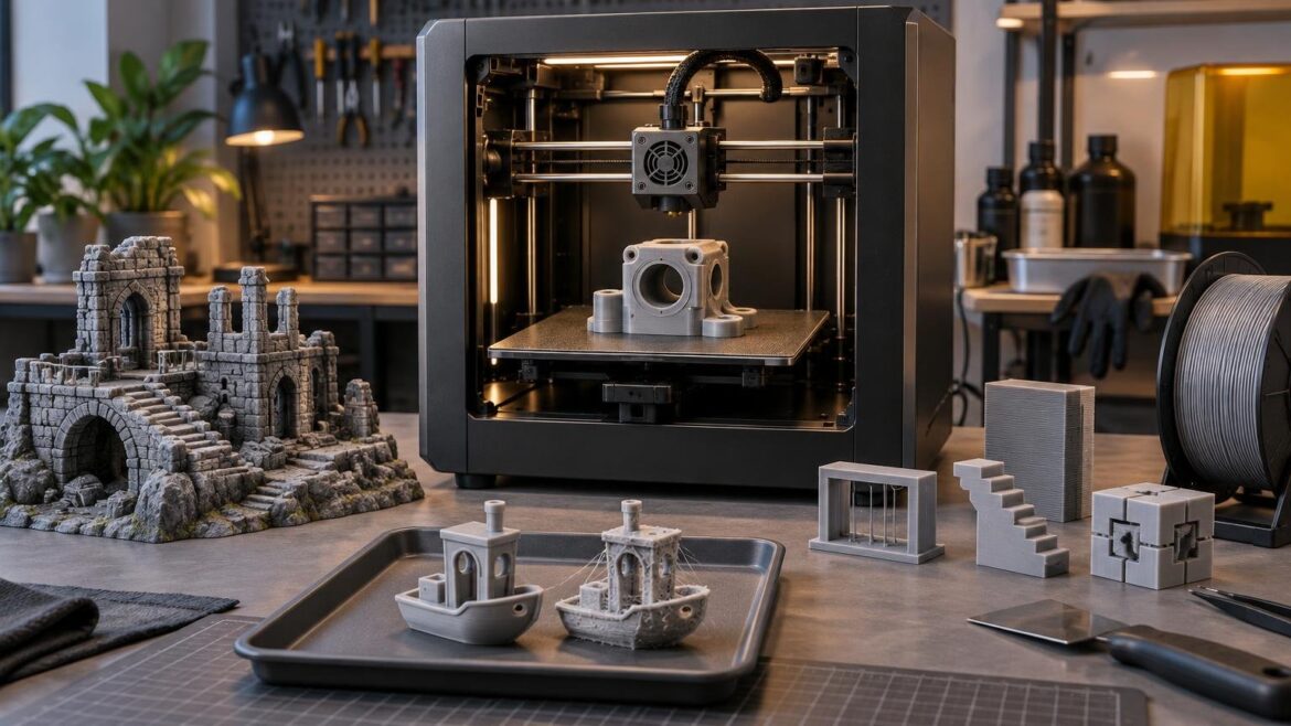
TLDR: If you want to know how to benchmark FDM 3D printers fairly, do not rely on one calibration toy. Run separate stock and calibrated tracks, lock the material and slicing variables, test individual geometric features, and then print representative terrain and functional parts. Report measurements, visual observations, print time, material use, failures, and interventions separately rather than hiding everything inside one score.
A small all-in-one model can reveal obvious cooling, extrusion, or motion problems, but it cannot represent every job a printer will face. A useful benchmark needs both controlled diagnostics and real projects. The diagnostics identify why a machine struggles; the projects show whether those strengths and weaknesses matter during practical use.
How to benchmark FDM 3D printers fairly
Start by defining the job. An FDM printer might be expected to make dimensionally accurate brackets, detailed tabletop terrain, quick prototypes, large enclosures, or batches of small parts. No single object establishes total capability across all those workloads.
That is consistent with the broader idea behind ISO/ASTM 52902:2023 for geometric capability assessment, which addresses the use of test artefacts to assess additive manufacturing systems. The standard supports structured geometric assessment, but it should not be represented as prescribing one universal collection of printer settings or one complete consumer review procedure.
A practical review protocol should answer five separate questions:
- Can the printer produce controlled geometric features accurately?
- What quality does a buyer get from the normal stock workflow?
- How much does sensible calibration improve the result?
- Can the printer complete representative projects without excessive cleanup or intervention?
- What speed and material cost accompany an acceptable result?
Keeping those questions separate prevents a fast but rough print from defeating a slower usable one. It also prevents a beautifully tuned result from being presented as the experience a new owner receives out of the box.
Lock the variables before printing
Comparison becomes meaningless when one printer receives dry premium filament and extensive tuning while another uses an old spool and a generic profile. Record the complete test configuration before starting, and preserve the project files and generated G-code where licensing permits.
| Variable | Control and disclosure rule | Why it matters |
|---|---|---|
| Printer | Record model revision, firmware, nozzle diameter, build surface, enclosure state, and installed upgrades. | Hardware revisions and modifications can change the result. |
| Filament | Use the same material line, color, batch where practical, conditioning method, and storage procedure. | Moisture and formulation affect extrusion, stringing, bridging, and finish. |
| Slicer | Record software version, profile source, layer height, wall count, infill, speeds, acceleration, cooling, temperatures, and flow. | A printer result is partly a slicing and profile result. |
| Model | Archive the exact file revision, orientation, scale, support policy, and checksum or equivalent identifier. | Silent model changes destroy repeatability. |
| Environment | Record ambient temperature and whether doors, lids, or draft protection were used. | Warping and cooling can vary with the test environment. |
| Measurement | Define the instrument, its resolution, measurement locations, repeat count, and rounding rule. | Numbers are not comparable without a consistent method. |
| Failures | Count every started job and record retries, interventions, discarded output, and recovery behavior. | Quietly rerunning failures exaggerates reliability. |
Standardize the core comparison around one common configuration, such as a 0.4 mm nozzle and a declared layer height. A 0.6 mm terrain or high-throughput test can be valuable, but it belongs in a separately labeled track. The same rule applies to different materials: PLA results should not be generalized to PETG, ABS, ASA, TPU, or fiber-filled composites.
Publish stock and calibrated results separately
The cleanest protocol has two modes. Baseline mode measures the normal buyer experience. Controlled mode measures what the machine can do after a documented, reasonable tuning process. Never average the modes together.
Baseline or stock mode
Use the current manufacturer slicer and supplied profile when available. Permit automated routines that are part of the printer’s normal setup or are explicitly requested before a print, including automatic bed leveling, nozzle cleaning, resonance checks, and automatic flow checks. Record which routines ran. Do not manually edit flow, pressure advance, temperature, retraction, speed, or cooling to rescue the result.
This policy treats built-in automation as part of the product while preventing undisclosed expert tuning. If an automated routine is optional, note whether it is enabled by default and how much time it adds.
Calibrated or controlled mode
Use a fixed calibration sequence and publish every resulting change. OrcaSlicer’s documented calibration resources cover temperature, flow, pressure advance, retraction, and maximum volumetric speed, making them a useful basis for a disclosed sequence even if another slicer is used for the final jobs.
A fair controlled track changes only defined parameters and stops after a fixed time or number of iterations. Otherwise, familiar machines may receive hours of attention while less familiar models receive only cursory tuning. Report both the tuning time and the final profile.
Build the core suite from targeted tests
Combined torture tests are convenient, but one failed region can disturb another and make diagnosis difficult. The Kickstarter and Autodesk FDM assessment material separates features including dimensional accuracy, bridging, overhangs, fine features, resonance, and Z-axis behavior. Targeted models make it easier to isolate those limits rather than infer everything from one crowded object.
| Test | What to record | Recommended interpretation |
|---|---|---|
| First-layer patch | Coverage, gaps, ridges, edge lift, automated setup time, and intervention. | Shows bed mapping and first-layer workflow, not overall print quality. |
| Bridge ladder | Longest predefined span meeting the published droop and strand-cohesion limit; photograph the underside. | Tests cooling and extrusion across unsupported spans. |
| Overhang sweep | Steepest predefined angle meeting the published roughness and curl criterion. | Shows where unsupported surfaces become unacceptable. |
| Dimensional coupon | X, Y, and Z external dimensions plus hole diameters at fixed locations. | Separates external size error from undersized-hole behavior. |
| Clearance gauge | Smallest clearance that releases and moves without tools. | Provides a practical fit result without pretending to measure every assembly type. |
| Motion and detail specimen | Ringing distance, corner condition, seam visibility, thin-feature completion, and surface photographs. | Exposes motion artifacts and fine-feature limitations. |
| Flatness coupon | Gap or deviation measured at specified points after a fixed cooling period. | Useful for mounting faces and broad functional parts. |
Set acceptance thresholds before the printers are tested. For example, define the allowed bridge droop, the exact overhang angles, the clearance steps, and what qualifies as free movement. The particular threshold can be chosen to match the publication’s audience; consistency matters more than selecting a flattering cutoff after seeing the prints.
For caliper measurements, mark the measurement locations on a diagram, take repeated readings at those locations, and disclose instrument resolution. Report the individual readings or their defined average rather than adding more decimal places than the tool supports. Holes, external dimensions, Z height, and flatness should remain separate because one correction value will not necessarily improve all four.
Keep 3DBenchy as a reference, not the whole benchmark
3DBenchy remains useful because it is recognizable and contains several identifiable features. Its official reference material provides nominal dimensions and calls out features including a 40-degree bow overhang and a cabin-roof bridge. That makes it helpful for visual comparisons and for spotting major profile problems.
It is still only one small model in one orientation. A good Benchy does not prove that a printer can hold a broad functional part flat, complete a long terrain plate, maintain hole tolerances, or recover from a filament problem. Print it as a familiar supplemental reference, but do not make it the primary score.
Add a terrain workload that behaves like a real project
A fixed terrain model adds demands that short diagnostic coupons miss: a broad footprint, repeated texture, roofs or arches, long travel paths, seams on visible walls, and enough duration for heat or feeding problems to emerge. Modular terrain can also test whether connectors and adjoining surfaces fit after printing.
Choose one model or small model set with stable availability and clear permission for benchmark use. Freeze the exact revision, orientation, scale, support strategy, and plate layout. If the model changes, begin a new results series rather than quietly mixing revisions.
Record terrain performance in distinct fields:
- Texture readability on walls, stone, timber, and other repeated surfaces
- Condition of arch undersides, roofs, and unsupported ledges
- Seam placement and visibility
- Warping or lifted corners across the footprint
- Support scars and cleanup time
- Connector or tile fit using a predefined pass/fail procedure
- Slicer estimate, measured elapsed time, and reported material use
- Job completion, retries, and every user intervention
Use standardized photographs with consistent lighting, camera position, background, and magnification. Include visible walls and difficult undersides. Visual descriptions such as “obvious ringing under side light” are valid documented observations; they should not be disguised as instrument measurements.
Large terrain plates also help expose the workflow implications discussed in our guide to large-format 3D printers, where usable bed area and long-print behavior matter as much as nominal build dimensions.
Use a functional assembly to test practical fit
The functional workload should be an assembly rather than a decorative shape. A small bracket-and-pin mechanism, bolted enclosure corner, sliding joint, or two-part fixture can test mounting-face flatness, hole fit, mating clearance, wall integrity, support requirements, and cleanup.
Define success before printing. Record whether the parts assemble without sanding, drilling, heat, or forced fitting; whether the intended joint moves; and whether mounting surfaces sit as designed. If post-processing is permitted, time it and report it rather than treating the work as invisible.
Do not infer mechanical strength from appearance. A load-bearing comparison requires a controlled specimen, material condition, orientation, slicing configuration, loading apparatus, sample count, and failure definition. Without that procedure, the defensible result is limited to geometry, assembly, and observed wall integrity.
Measure speed only at acceptable quality
Use measured wall-clock time from the start of the job workflow to completion, while also reporting machine-reported and slicer-estimated times where available. State whether setup routines, heating, and cooldown are included. This reveals workflow overhead that a headline motion speed cannot.
Speed should be compared at a shared quality requirement. If one printer finishes earlier but fails the bridge threshold, produces an unusable mating fit, or needs a rerun, its first completion time is not equivalent to a slower successful job. Publish time, quality results, and failures as separate data, then explain the tradeoff.
Track reliability across multiple jobs
One successful overnight print is evidence that the printer completed that job, not proof of general reliability. Establish a fixed review window—for example, a declared number of job starts and minimum printing hours—and use the same rule for every machine. The precise window is an editorial protocol choice, not a universal standard.
Count every initiated print in the denominator. Classify the outcome as completed, completed with intervention, failed and recovered, or failed and restarted. Log adhesion loss, clogs, feed errors, layer shifts, thermal interruptions, software disconnections, and user mistakes separately. A rerun may demonstrate recovery, but it does not erase the original failure.
Reliability should also remain distinct from long-term service life. Belts, fans, nozzles, build surfaces, and other components age on different schedules, as explained in our guide to how long a 3D printer lasts. A review-period completion rate cannot predict years of ownership by itself.
Publish the data behind the verdict
A summary score can help readers scan results, but it should never replace the measurements. Publish the stock and calibrated profiles, model revisions, photographs, raw dimensions, completion records, elapsed times, material figures, and intervention log alongside any score.
Keep the result categories visible rather than forcing everything into a single winner:
- Geometry: external dimensions, holes, Z height, flatness, and clearance
- Unsupported printing: bridge and overhang outcomes
- Surface quality: seams, ringing, texture, and fine features
- Project utility: terrain quality and functional assembly result
- Throughput: elapsed time and material used for acceptable output
- Workflow: setup, calibration, support removal, and cleanup time
- Reliability: starts, clean completions, interventions, failures, and recovery
Label manufacturer specifications as manufacturer-reported. Do not place an advertised speed, tolerance, or build volume in the measured-results column unless the review actually measured it under the stated conditions.
The practical benchmark standard
The strongest FDM benchmark is not the one with the most calibration toys. It is the one another reviewer could reproduce and a buyer could interpret. Lock the variables, separate stock from calibrated performance, use targeted diagnostics to find weaknesses, and confirm practical value with terrain and a functional assembly.
The next step is to freeze the house test files and pass criteria before evaluating another printer. Once the models, profiles, measurement points, photo setup, and failure rules are fixed, comparisons become clearer—and a printer can win for the work it actually does well rather than for producing one impressive little boat.
References
- ISO/ASTM 52902:2023 – Additive manufacturing — Test artefacts — Geometric capability assessment of additive manufacturing systems
- Calibration · OrcaSlicer/OrcaSlicer Wiki · GitHub
- kickstarter-autodesk-3d/FDM-protocol/README.md at master · kickstarter/kickstarter-autodesk-3d · GitHub
- Home · kickstarter/kickstarter-autodesk-3d Wiki · GitHub
- #3DBenchy
#3DBenchy is 3D model specifically desi